Categories
Tech

MegaSquirt 3 Digital Dash

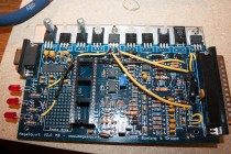
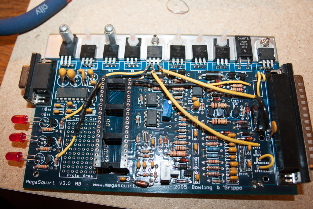
I am pleased to introduce a little side project that I have been working on the past few months. The projects initial main focus is to create a HD digital dashboard for the MegaSquirt ECU, to be built using as much off the shelf hardware as possible. This means that hopefully with some conscious design planning it should be possible to produce copies fairly easily just by following some documentation and ordering a few bits of the Internet here and there (This is the plan at least, who knows how things will pan out). Theres no reason other ECUs can’t also be supported in the future, however thats the only aftermarket ECU I have at hand and since thats what I run in my cars.

Project Brief

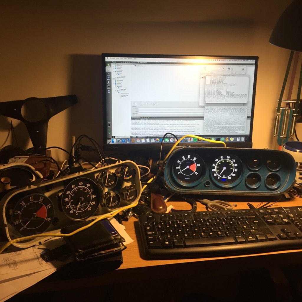
Create a digital dashboard that respects the character and history of the original cluster gauge, whilst also providing access to additional sensor readings that are important for any turbocharged engine.

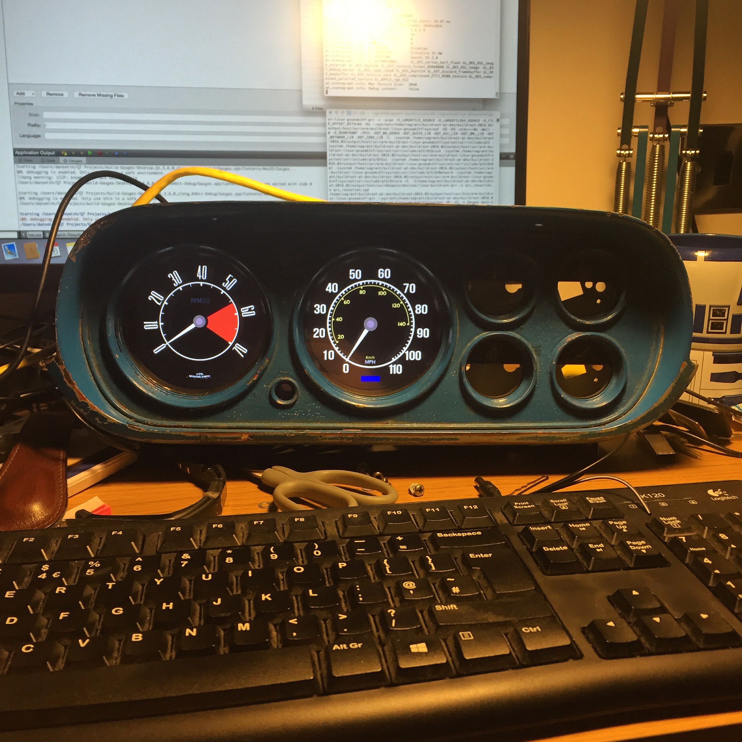
And so after a bit of hard work this is what I have come up with for now..

Mk1 Escort Digital Dash
The original dash is on the left (front cover removed)

The dash features an 8 inch 1080P LCD display powered by a Raspberry Pi 2 (soon to be RPi 3) running a stripped down build of Linux to allow for fast booting. The dash communicates with the cars MS3 ECU via CAN bus and will include some additional power features that allow it to turn on/off safety via a switched ignition input.

The main motivation for having a digital dash is to take advantage of displaying all the extra sensor data the MS3 ECU utilises and accumulates. There are sensor outputs and ECU calculations that I would be interested in knowing whilst driving, but at the same time I don’t with to clutter the dash with additional gauges and dials as that would spoil the general aesthetics of the interior. Creating a digital dash in the same style as the original dials is a good compromise on having access to the data and not ignoring the originality of the car.

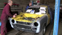
The development and install of the first dashboard will be a prototype version retrofitted into my Mk1 Escort. This type of instrumentation is something that I have wanted for many years, however it wasn’t until recently that I felt I had gained the right knowledge sets and courage to attempt such a project and not forgetting the funds to back. Believe me when I say this has been a long time in the works.

I will post more details on the project in the upcoming weeks but for now just wanted to give a glimpse into some of the more complicated long term projects I’m working on.

Categories
Tech

Ford Escort Xflow Turbo First Start – VIDEO

Categories
Automotive

MS3 EDIS 4 wasted spark

The additional BIP373 arrived in the post today. I needed to find a space to install the extra driver within the Megasquirt casing. I decided to remove one of the large sense resistors (R38) from the heat sink to make space for the new ignition drivers.

I figured this would be okay to remove as I am only intending to use one single large injector (750cc), meaning the second injector bank won’t be used (which R38 protects).

BIP373 Additional Ignition Driver MS3

Categories
Automotive

Damn you Wasted Spark

1st Generation Ford EDIS 4 Coil Pack

I have been working on the ignition output of the Megasquirt today, however have ran into a few snuggles. It was briefly decided many months ago that we would initially use a Ford EDIS-4 coil-pack running a wasted-spark, combined with a VR sensor pinched from a scrap Zetec engine. Upon the initial build of Megasquirt I saw a few entries related to EDIS style ignition setups and thought nothing more as I wouldn’t have to cross that bridge until we install it in the car.

That time has now arrived haha. Upon re-reading the MegaSquirt 3 assembly documents, the EDIS setups mentioned there utilise an individual unit that is separate from the main MegaSquirt, known as the EDIS module. This module combines the tach input from the VR sensor and coil driver ignitions into a single unit. From my understandings, the module sends a tach signal to the MegaSquirt in a format similar to how Coil-Negative ignition works.

For our setup we aren’t using the EDIS module, instead I want to be able to run Direct Coil Control. Which removes the necessity of the EDIS module by connecting the VR sensor and EDIS coil directly to the megasquirt itself. Three reasons why I prefer this approach;

  1. I don’t have a spare EDIS module lying about.
  2. I want to avoid installing any extra ancillaries in the engine bay.
  3. The Megasquirt is capable of Direct Coil Control, so naturally I want to make use of it.

I already know that the EDIS-4 is two separate coil packs stuck together in a single unit and I already know that my Megasquirt comes included with a single coil driver. Upon further research on the Megasquirt forums I have come to the conclusion that I need to install an additional Bosch BIP373 Ignition Driver into the ECU. A quick search on Google for the Bosch part turned up on a few distributors in the UK, all of which were currently out of stock.Logged onto to DIYAutoTune where I knew they would have the part in stock, $19 total including delivery.

In hindsight, I would of ordered the extra ignition module when I first bought the MS3 kit in summer 2011. However back then we was only going to run a ‘Fuel-only’ setup, and that was also before we decided to run a turbo. Ohh how times have changed.

I will write another post relating to installation and testing of the driver, when the parts arrive from the States.

UPDATE: Follow on post can be found here.

Categories
Automotive

JimStim v1.5 stimulator board – Assembly

Today I did some soldering and constructed the JimStim V1.5 stimulator board. This nifty little board is a MegaSquirt simulator that enables you to bench-test your MegaSquirt ECU by simulating all the necessary sensor inputs required for the MegaSquirt to work.

The MegaSquirts sensor inputs can be easily tested using JimStim. This is achieved through using potentiometers to variate sensor voltages to be processed by the ECU.

JimStim is capable of simulating the following sensor outputs:

  • MAT (manifold air temperature)
  • CLT (coolant)
  • TPS (throttle position sensor)
  • O2 (O2/lambda sensor)

Included also is a nifty micro-controller that allows JimStim to simulate a toothed wheel sensor signal, which in turn simulates engine RPM. This feature is especially handy as you can confirm that your MegaSquirt operates correctly in what is effectively a controlled test environment. When building a MegaSquirt (especially if it’s your first time building) it can be a lifesaver in identifying any issues with your MegaSquirt that could potentially damage your expensive EFI kit, as well being a HUGE timesaver (I can’t empathise this one point enough) when it comes to physically wiring the MegaSquirt into your car. For example, if you were attempting a first-start after a new install and encountered issues with establishing a stable RPM sync, you could can during testing that the MegaSquirt you built works perfectly and that the issue must lie somewhere else within the car.

JimStim can be purchased from DIYAutoTune as a unassembled kit for you to solder together, or as a ready-to-go preassembled board.

Here are a few shots of soldering together my JimStim.

wpid706-20110705-_MG_1266.jpg

wpid707-20110705-_MG_1267.jpg

wpid709-20110705-_MG_1268.jpg

wpid690-20110705-_MG_1270.jpg

wpid692-20110705-_MG_1275.jpg

wpid694-20110705-_MG_1279.jpg

wpid696-20110705-_MG_1280.jpg

wpid698-20110705-_MG_1281.jpg

wpid700-20110705-_MG_1282.jpg

wpid702-20110705-_MG_1284.jpg