Categories
Tech

Setting up PiDuino with Raspbian Buster

Years ago I bought myself a PiDuino from SK Pang with the original intention of using it as a power management board for my digital cluster project (ended up using a SleepyPi 2 in the end) and so hadn’t touched it for a few years, below are my notes on getting it working under Raspbian Buster on a RPi 3B+ in April 2020.

The original assembly guide is still relevant for soldering the board together, as well as the instructions for setting up and testing the software, especially Gordons instructions

In summary I performed the following:

Install Arduino and installed a modified version of avrdude (this might not be needed anymore as the standard avrdude could work, but didn’t test).

sudo apt-get update && sudo apt-get upgrade
sudo apt-get install arduino

cd /tmp
wget http://project-downloads.drogon.net/gertboard/avrdude_5.10-4_armhf.deb
sudo dpkg -i avrdude_5.10-4_armhf.deb
sudo chmod 4755 /usr/bin/avrdude

Next regain control of the serial port by removing console=ttyAMA0,115200 from ‘/boot/cmdline.txt’

sudo nano /boot/cmdline.txt

We also need to edit ‘/boot/config’ and add a couple lines to reconfigure the serial port

sudo nano /boot/config.txt

And then add at the bottom:
dtoverlay=pi3-disable-bt
uart_enable=yes

Then stop the Systemd getty service and disable it from starting on boot with, followed by a reboot

sudo systemctl stop serial-getty@ttyAMA0.service
sudo systemctl disable serial-getty@ttyAMA0.service
sudo reboot

Then following more instructions from Gordon, add the custom board and programmer entries into Arduino (you might be able to get away with just adding the custom programmer entry if you’re just interested in flashing the PiDuino using the RPi pins).

cd /tmp
wget http://project-downloads.drogon.net/gertboard/boards.txt
wget http://project-downloads.drogon.net/gertboard/programmers.txt
cd /usr/share/arduino/hardware/arduino
sudo mv boards.txt board.txt.bak
sudo mv /tmp/boards.txt .
sudo mv programmers.txt programmers.txt.bak
sudo mv /tmp/programmers.txt .

With that all the software should be setup ready for use, connect the Piduino to the RPi header and fire up Arduino.

Set Tools -> Board -> Arduino Pro or Pro Mini (3.3v, 8 MHz) w/ ATmega328

Set Tools -> Programmer -> Raspberry Pi GPIO

You can now upload example programs such as ‘Blink’ to test that the upload functionality is working okay, be sure to use upload using programmer instead of just clicking the regular upload button

Select File -> Upload using programmer

When I did this I found that the example ‘blink’ project was running but very very slow, taking approximately 5 sec’s for the LED to blink. This can occur when the bootloader hasn’t been set, this is easy to fix by burning the boot loader.

Select Tools -> Burn Bootloader

With that the blink project should blink at the correct speed and everything is all setup and ready to go.
Categories
Tech

Deck Chair Repair (using a 3D printer)

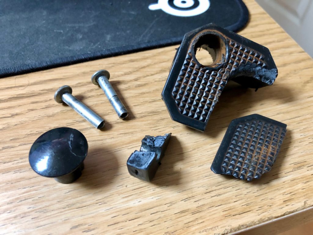
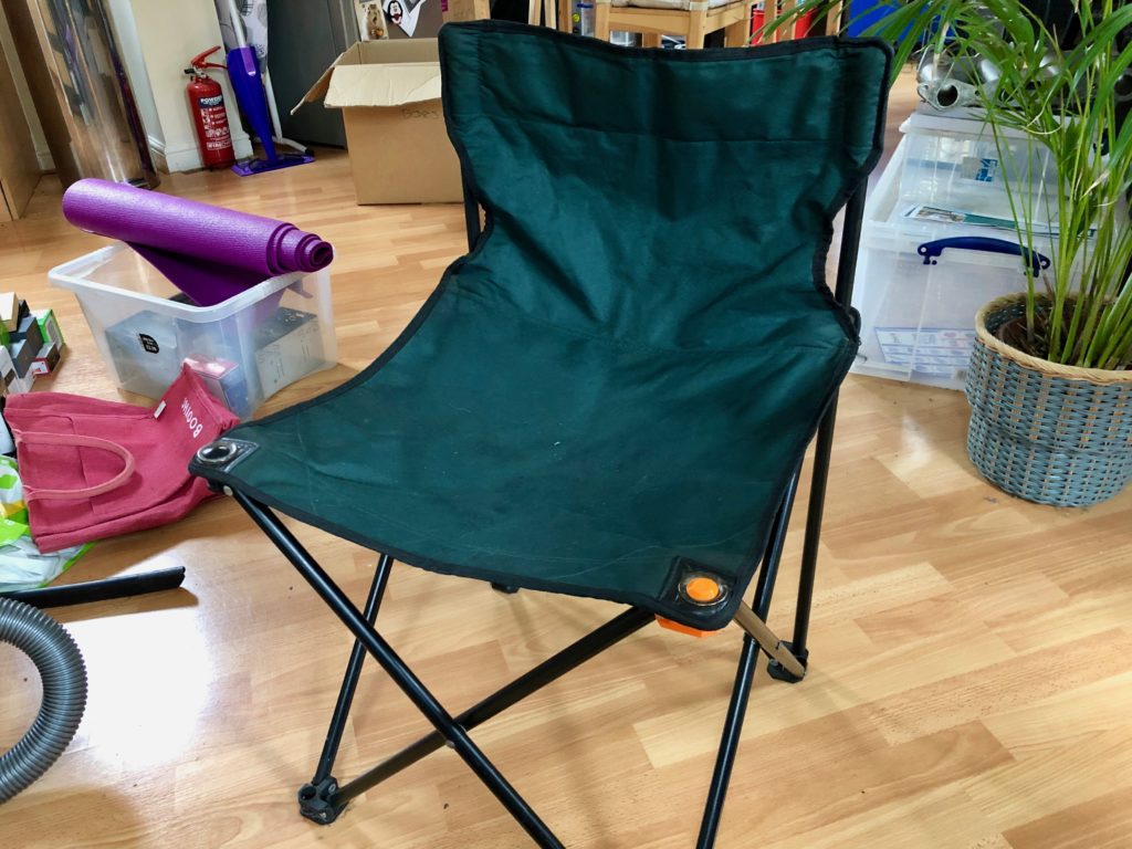
One of the folding chairs (aka thinking stools) I have in the garage broke recently, rather than chuck in the bin I thought it would be good practice to 3D model replacement parts and then make using a 3D printer. By good practice, I mean testing my Fusion360 skill are ‘good enough’ to the point where it would be more cost effective to model/print versus simply buying a new chair, depends on how much you value your own time I guess.

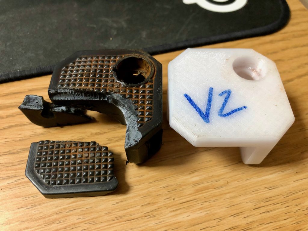
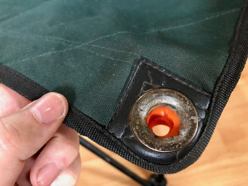
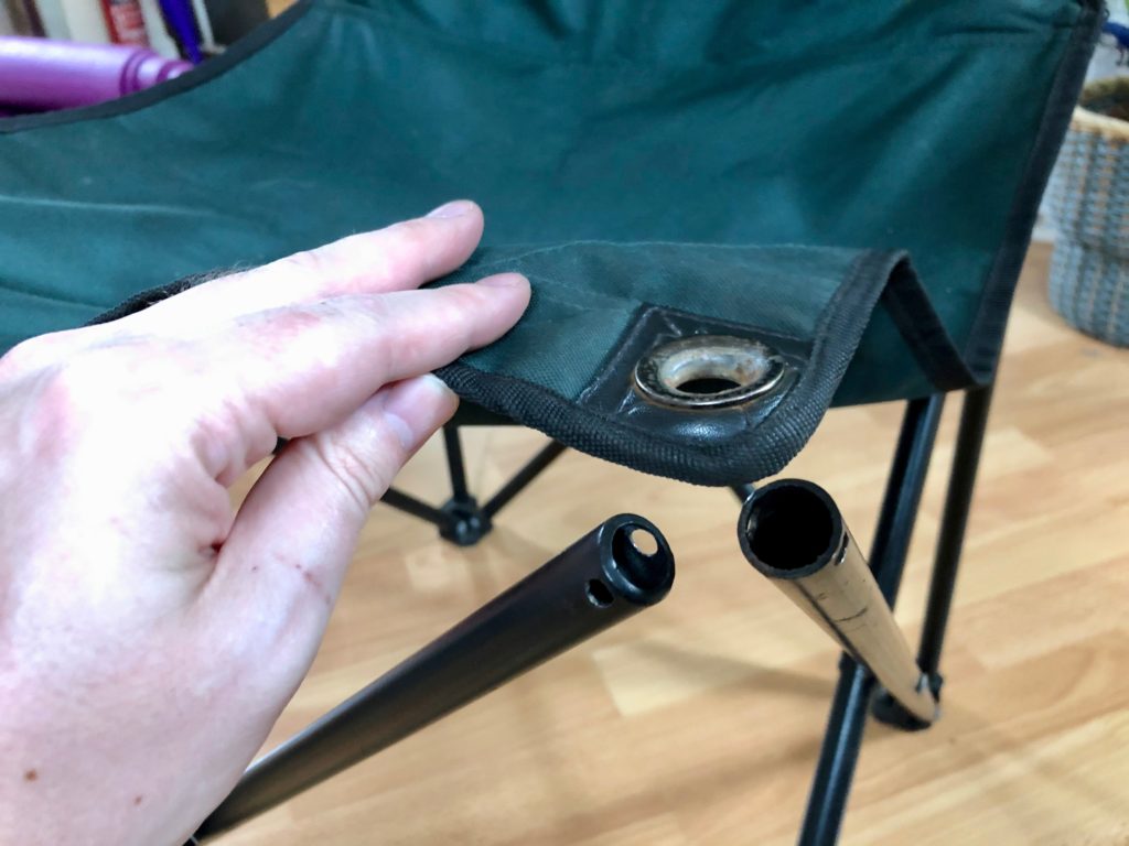
One of the corner brace/brackets snapped off
The original bracket was held in place using rivets
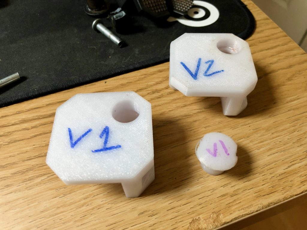
The design went through a few iterations, was happy to have gotten majority of the design right in v1
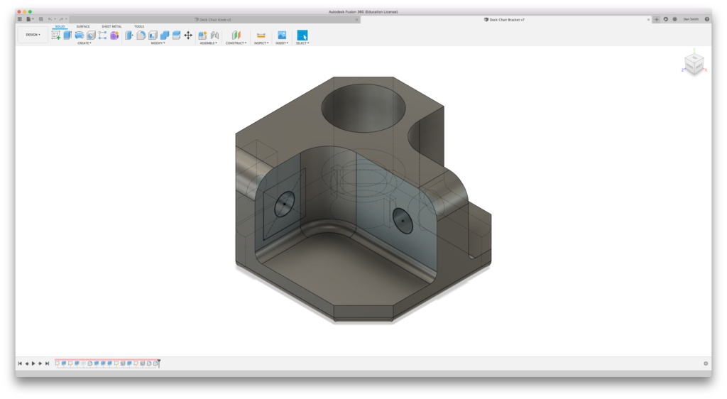
Model I created of the bracket in Fusion360 (bracket is upside down in screenshot)
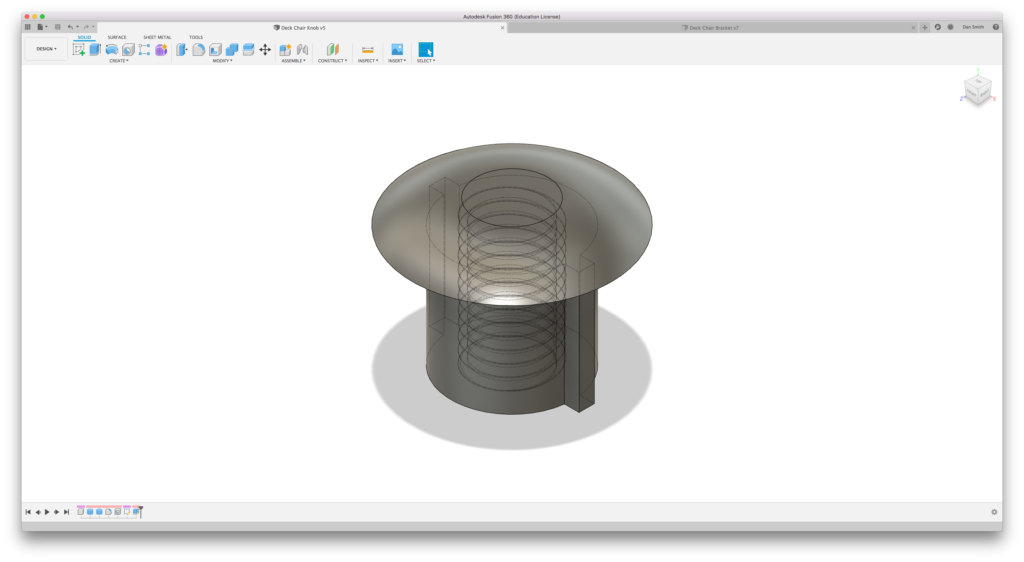
Top piece which inserts into main bracket, you can see the M8 thread modelled internally.
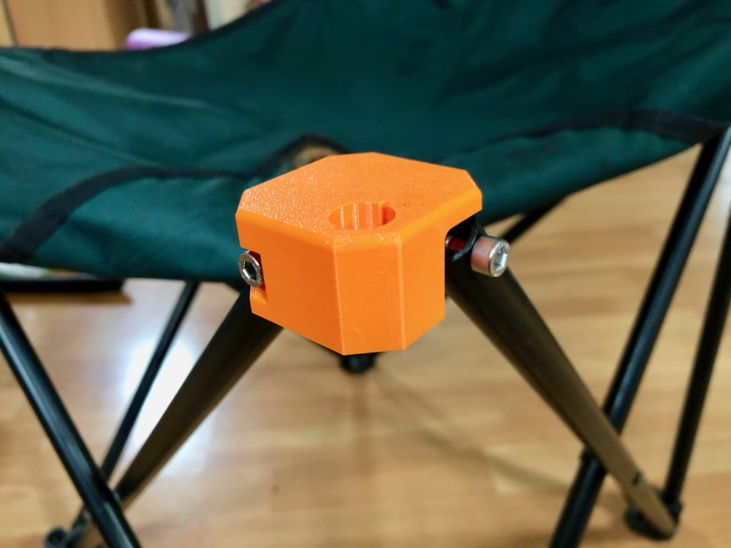
Ready for functional testing
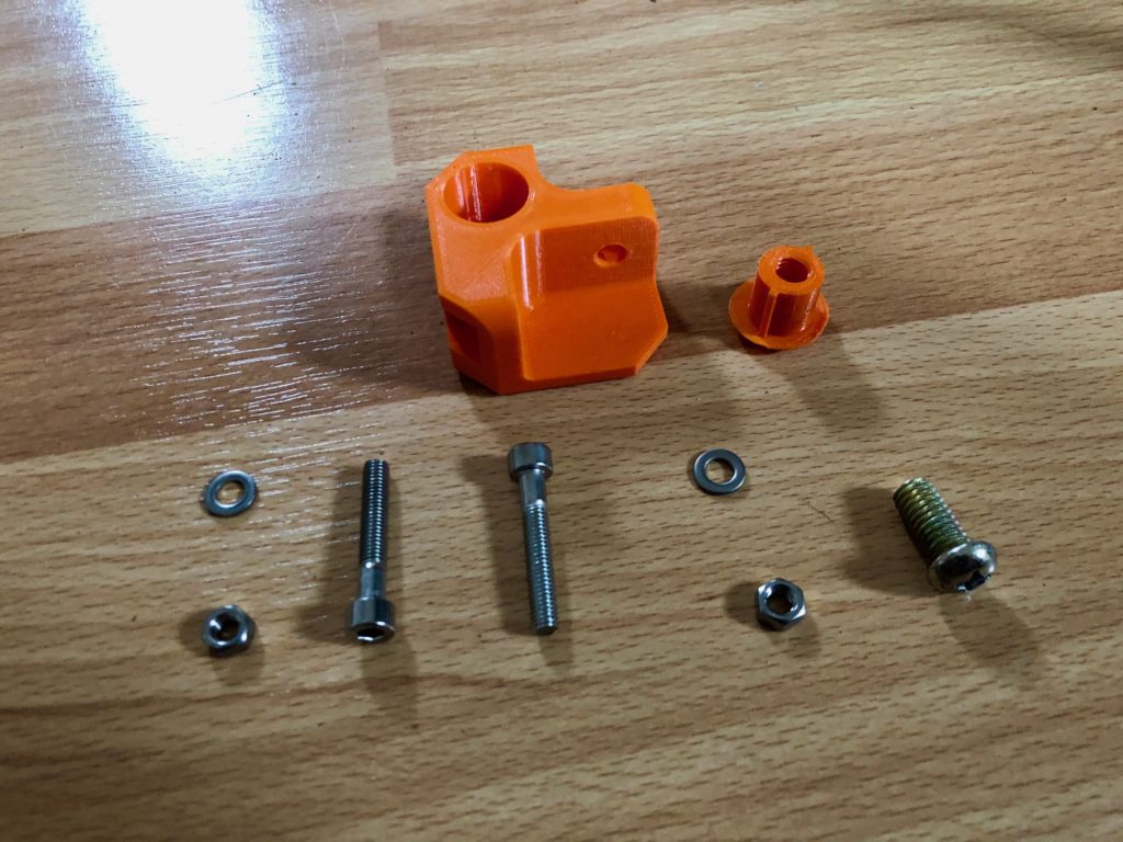
Used bolts in place of rivets, probably should of also used nylock nuts
Had to open up the holes left from the rivets in order to get the bolts to fit
The mushroom sleeve plastic thing has a bolt that screws in underneath which grips the chairs material, this was printed with an M8 x 1.5mm thread modelled by Fusion360, the M8 bolt screwed into the printed thread just fine.
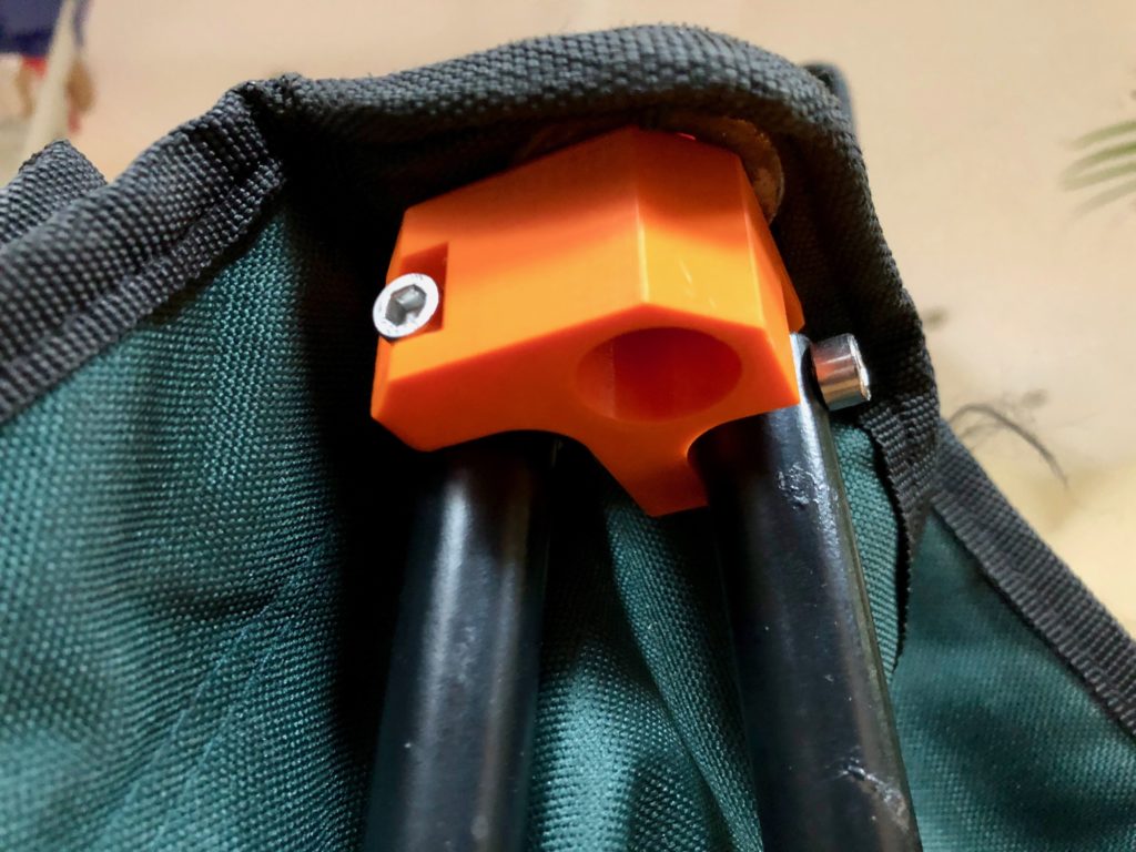
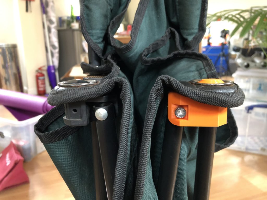
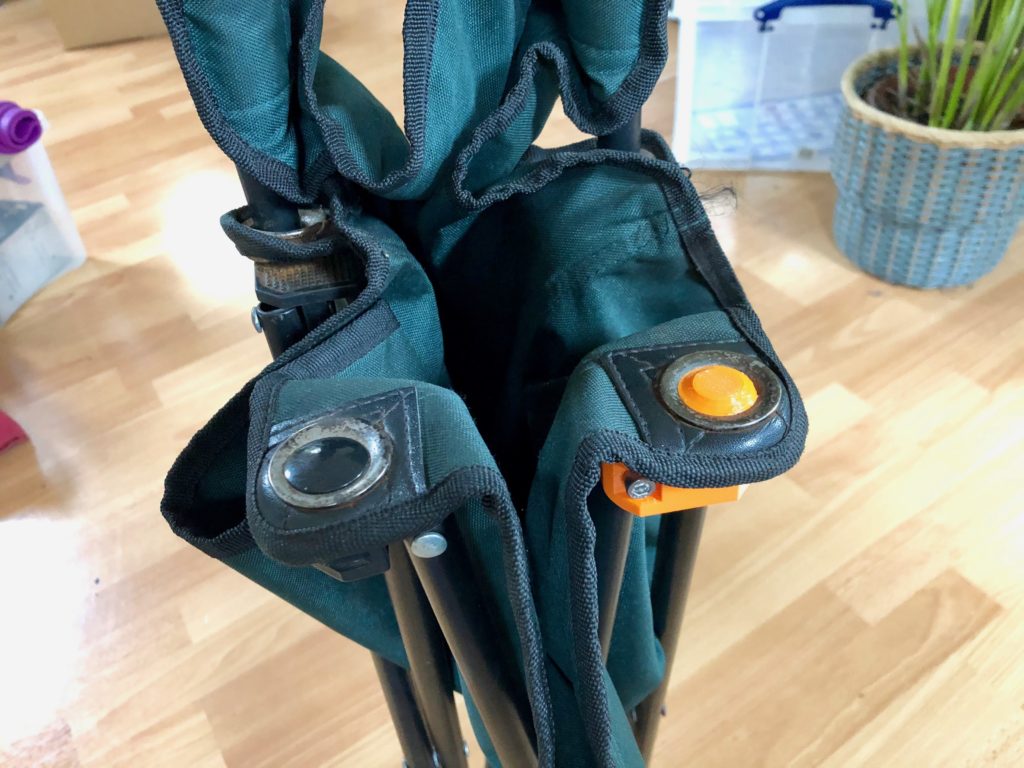
The finished piece, probably should have printed this in Carbon Fibre reinforced Nylon as its a structural part taking the full weight of a person. Will be interesting to see how long it holds currently as PETG.

In the end it probably was about half an hours modelling time, and a few hours print time for a total of 3 iterations, it was worth it in the end just as a fun experiment, turns out I can model pretty quick when I have to.

Categories
Computers

AWS Glacier Delete All Archives in Vault

Ran into an annoying issue where I wanted to delete an old AWS Glacier Vault, but AWS won’t let you delete a Vault and all containing archives, instead you must first delete all archives and only then can you delete the vault.

AFAIK there isn’t anything in the AWS CLI tools to accomplish this and couldn’t find any lightweight tools, so hashed together a small python script to do the job.

The script reads the json output file (output.json) you can generate for a vault which contains a list of all the archives in that particular vault (can’t remember the exact AWS CLI command to do this) and then goes through and simply deletes the archives one by one. After a few hours have passed the vault should be empty and can be deleted.

Script can be found here: https://github.com/bytesandbolts/delete-aws-glacier-archives

Categories
Automotive

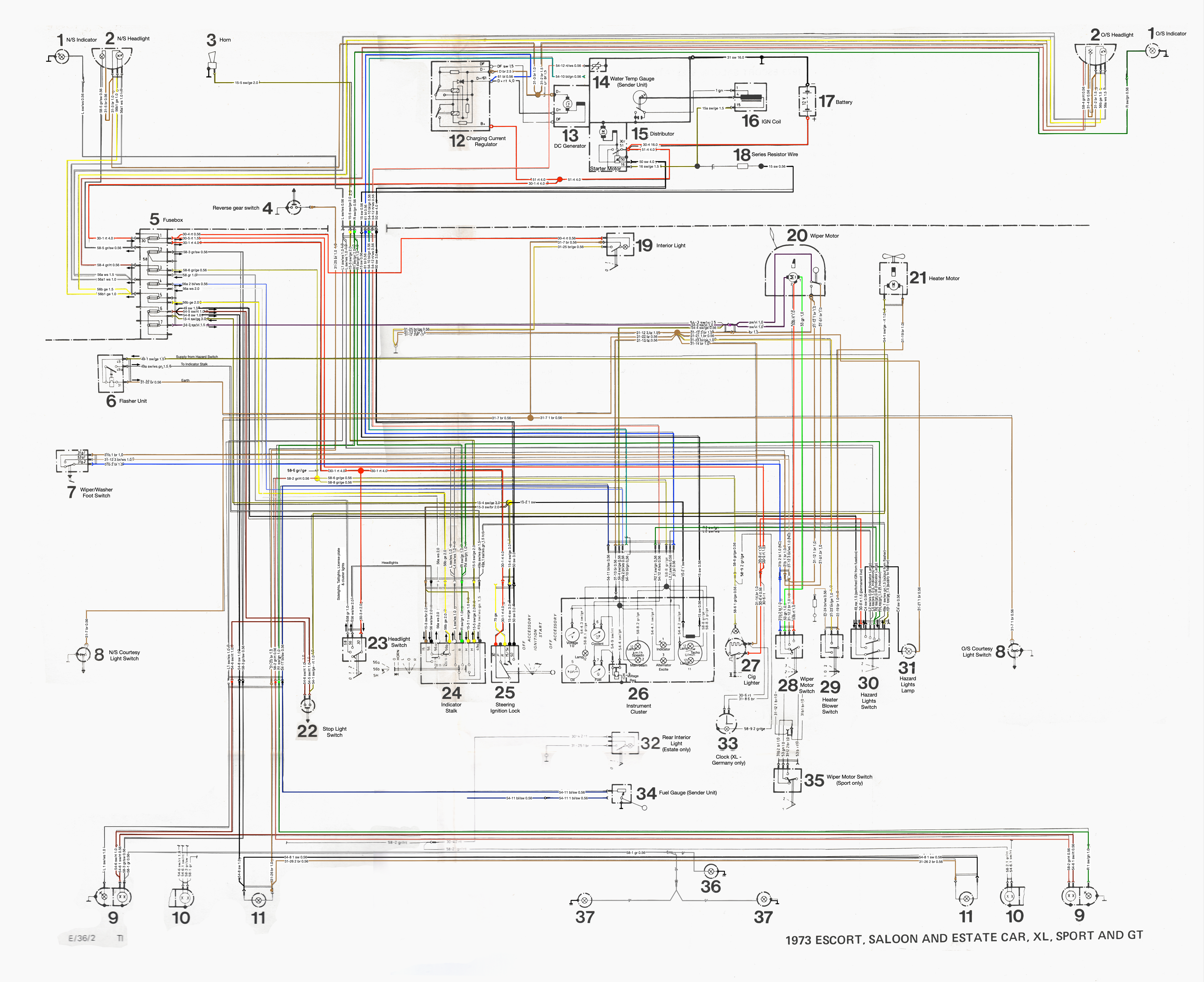
MK1 Escort RHD Colour Wiring Diagram

This my improved version of a Ford Mk1 Escort RHD Wiring Diagram that I decided to colour to improve readability. 

Save this image to your computer to view in full resolution. 

Categories
Tech

Swap Speaker Output Channels in macOS

How my cheapo Logitech speakers are setup on my desk in relation to my Hackintosh computer means the right speaker is actually on the left side of my side and the left is on the right. This is due to the 3.5mm input cable built into the right speaker not being long enough to reach the computer when positioned on the right side.

Luckily within macOS, Apple make it super easy to switch output channels, so left is right and right is left.

From Finder open the Audio MIDI Setup app which can be found in
Applications -> Utilities -> Audio MIDI Setup.app

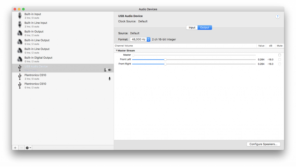
  1. Select your current output device, in my case this is ‘USB Audio Device’ but yours will likely be ‘Built-in Output‘.
  2. Click ‘Configure Speakers‘ located at the bottom right.
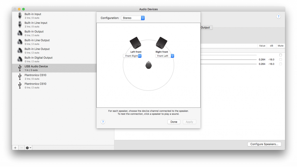
  3. Then it’s simply the matter of setting the left front to the front right and the right front to the front left.
  4. Click ‘Apply‘ then ‘Done’ and close. 
  5. Test audio output channels are correct by finding a sound test video on YouTube.